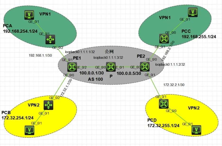
BPG MPLS VPN

2024 年 5 月 3 日 星期五(已编辑)
/
25
摘要
实验中进行了操作步骤如下: 1. 运行 OSPF 和 MPLS 在公网区域 2. 创建本地 VPN,并绑定到 CE 的端口上 3. 配置 PE 与 CE 之间的路由协议 OSPF 4. 配置 MP-BGP 5. 配置本地 VPN 与 MP-BGP 的引入导出 6. 将私网路由引入 PE 与 CE 之间的路由协议。
这篇文章上次修改于 2024 年 5 月 7 日 星期二,可能部分内容已经不适用,如有疑问可询问作者。

实验图
image.png

image.png

实验操作

操作步骤: 1.先在公网区域运行 OSPF 以回环地址为路由器 ID

PE1:
ospf 1 router-id 1.1.1.1
area 0
network 1.1.1.1 0.0.0.0
network 100.0.0.1 0.0.0.3

PE2:
ospf 1 router-id 1.1.1.2
area 0
network 1.1.1.2 0.0.0.0
network 100.0.0.6 0.0.0.3

P:
ospf 1 router-id 1.1.1.3
area 0
network 100.0.0.2 0.0.0.3
network 100.0.0.5 0.0.0.3

2.公网内部开启 mpls 和 mpls ldp 以回环地址为 ID

PE1;
mpls lsr-id 1.1.1.1
mpls ldp

int g 0/0
mpls enable 
mpls ldp enable

PE2:
mpls lsr-id 1.1.1.3
mpls ldp

int g 0/0
mpls enable 
mpls ldp enable

P:
mpls lsr-id 1.1.1.2
mpls ldp

int g 0/0
mpls enable
mpls ldp enable

int g 0/1
mpls enable
mpls ldp enable

3.创建本地 vpn

PE1:
ip vpn-instance vpn1
router-distingusher 100:1 
vpn-target 100:1 both

ip vpne-instance vpn2
router-distingusher 200:2
vpn-target 200:1 both

PE2:
ip vpn-instance vpn1
router-distingusher 100:1
vpn-target 100:1 both

ip vpn-instance vpn2 
router-distingusher 200:1
vpn-target 200:1 both

4.绑定到连接对应 CE 的端口上面

PE1:
int g 0/1
ip binding vpn-instance vpn1
int g 0/2
ip binding vpn-instance vpn2

PE2:
int g 0/1
ip binding vpn-instance vpn1
int g 0/2
ip binding vpn-instance vpn2

5.配置 PE 与 CE 之间的路由协议 OSPF

PE1:
ospf 10 vpn-instance vpn1
area 0
network 192.168.1.1 0.0.0.3

ospf 20 vpn-insatnce vpn2
area 0
network 172.32.1.1 0.0.0.3

CE1:
ospf 10
area 0
network 192.168.1.2 0.0.0.3
network 192.168.254.1 0.0.0.255

CE2:
ospf 20
area 0
network 172.32.1.2 0.0.0.3
network 172.32.254.1 0.0.0.255

PE2:
ospf 10 vpn-instance vpn1
area 0
network 192.168.2.1 0.0.0.3

ospf 20 vpn-instance vpn2
area 0
network 172.32.2.1 0.0.0.3

CE3:
ospf 10
area 0
network 192.168.2.2 0.0.0.3
network 192.168.255.1 0.0.0.255

ospf 20
area 0
network 172.32.2.1 0.0.0.3
network 172.32.255.1 0.0.0.255

6.配置 MP-BGP

PE1:
bgp 100
peer 1.1.1.2 as-number 100
peer 1.1.12 connect-interface l 0
address-family vpnv4
peer 1.1.1.2 enable

PE2:
bgp 100
peer 1.1.1.1 as-number 100
peer 1.1.1.1 connect-interface l 0
address-family vpnv4
peer 1.1.1.1 enable

7.配置本地 VPN 与 MP-BGP 的引入导出

PE1:
bgp 100
ip vpn-instance vpn1
address-family ipv4 unicast
import-route ospf 10
import-route direct

ip vpn-instace vpn2
address-family ipv4 unicast
import-route ospf 20
import-route direct

PE2:
bgp 100
ip vpn-instance vpn1
address-family ipv4 unicast
import-route ospf 10
import-route direct 

ip vpn-instance vpn2
address-family ipv4 unicast
import-route ospf 20
import-route direct

8.将私网路由引入 PE 与 CE 之间的路由协议

PE1:
ospf 10
import-route bgp

ospf 20
import-route bgp

PE2:
ospf 10
import-route bgp

ospf 20
import-route bgp
  • Loading...
  • Loading...
  • Loading...
  • Loading...
  • Loading...